Greetings everyone! In this blog post, we will be examining the process of migrating the NSX-V
to NSX-T environment, which has been integrated with vRA. We will be demonstrating the
migration procedure using the following software versions:
- NSX-V 6.4.12
- NSX-T 3.2.2.1
- ESXi, vSphere and vDS 7.0
- vRA 8.10.1
It is important to note that prior to deploying or updating your environment, it is recommended
that you consult the interoperability matrix for the version you are utilizing. This will guarantee
that your environment is well-prepared for the migration process. If you are planning to migrate,
we strongly advise that you check the matrix beforehand to ensure a seamless and successful
migration.
Prior to migration some of the main points, which needs to be taken care while verifying the NSX-V environment are mentioned below,
- Key aspects to address in this regard include the configuration status of the VXLAN port.If it is not already configured, it must be addressed to avoid any limitations arising from the migration coordinator.
- Additionally,the transport zone replication mode is set to unicast. If any other replication mode is set, make sure its changes to unicast. Reason limitation of migration coordinator.
- Notably,if the environment is cross vCenter then secondary NSX manager nodes is not supported on Migration coordinator.
- Making sure backup of NSX-V environement is taken.
So, once the environment pre-migration checks are done and compatible for the migration with above points are considered. Then we can follow the below information which will assist to migrate the NSX-V environment to NSX-T.
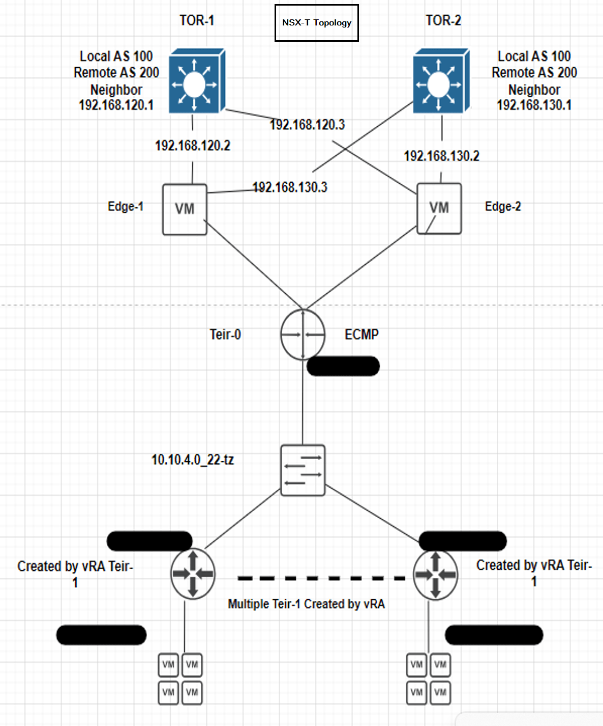
In this process we are following the Migration (MR) guide3.2. NSX-V with vRA User-defined topology
Below we can observe topology of NSX-V and NSX-T topology proposed will be seen once we complete the migration.

First step Preparing the NSX-T Datacenter Environment:
We must deploy a new NSX-T environment for this migration. We cannot merge vRealize Automation deployments from your NSX-V environment into an existing NSX-T environment, which is preconfigured and in-use.
Deploy one NSX-T appliance on the same vCenter where the NSX-V is running. Make sure don’t attach the NSX-T appliance interfaces to an NSX-V logical switch and to prevent the NSX-T appliance VM and other VMs in NSX-T from losing connectivity after the VMs are rebooted post migration, tag the VMs.
In our environment here on vCenter we have 2 clusters, Management and Compute. Therefore, the NSX-T appliance will be deployed on Management cluster and the Edges will be deployed on the Compute cluster.
Hence make sure you do the deployment as per the environment.
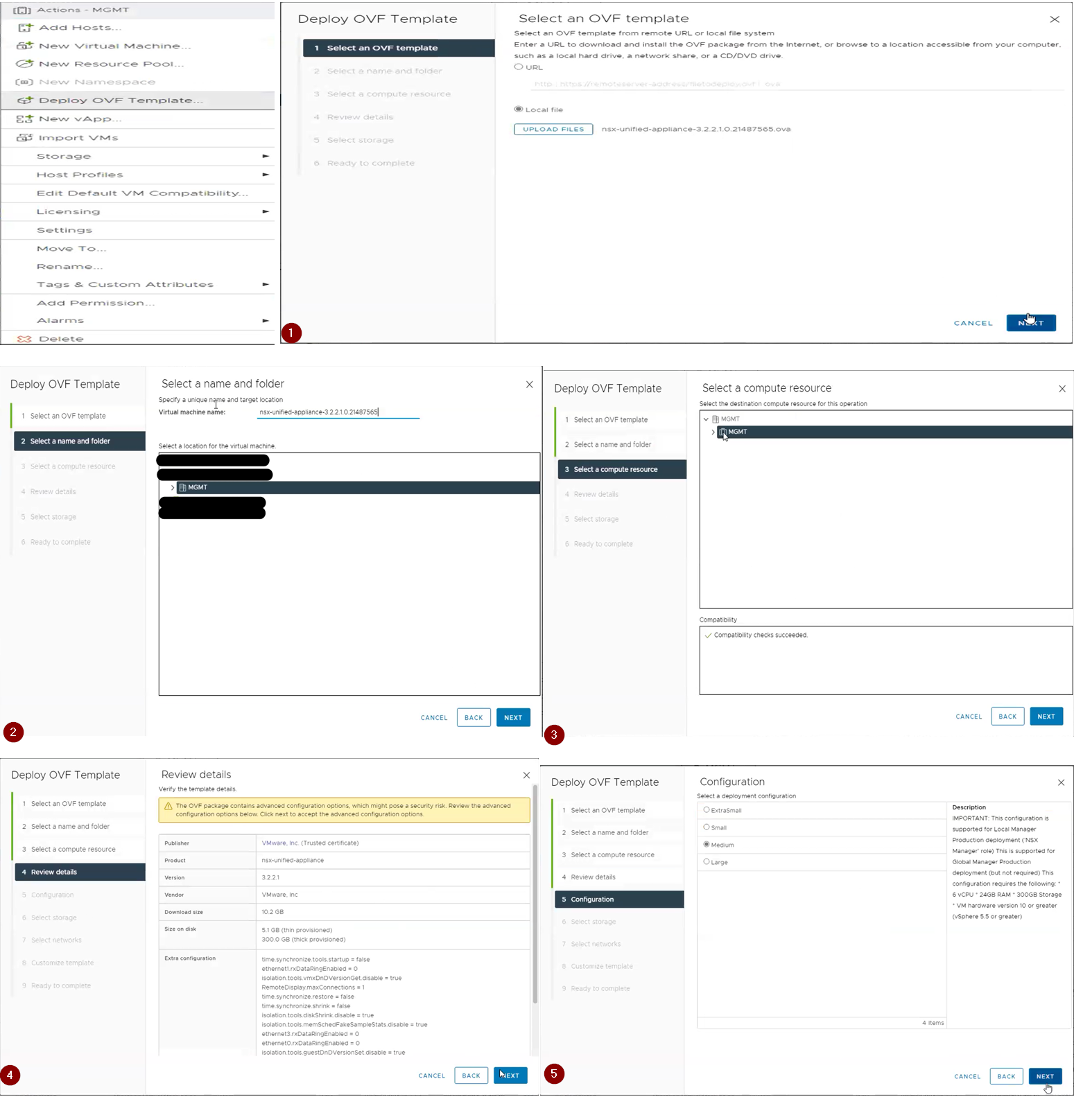
Below are the steps for deploying the NSX-T VM.
1.Select an OVF template here we go with 3.2.2.1 NSX-T.
2.Provide the VM name for the NSX-T.
3.Select the compute resource.
4.Reveiw the details
5.Select the deployment configuration (Small, Medium, Large or XLarge). Here we have used medium type.
6.Select the storage.
7.Select the network this is the management network which will be used to access the NSX-T using GUI, SSH. So, make sure you select the Management Network port group from which IP address will be given.
8. Customize Template. Here we provide the root, admin, audit passwords, IP address, gateway, DNS, hostname and NTP details.
9. Ready to complete. Review the details provided and hit finish.

Once the Appliance is deployed access it via GUI, login by providing admin credentials and follow the below steps.
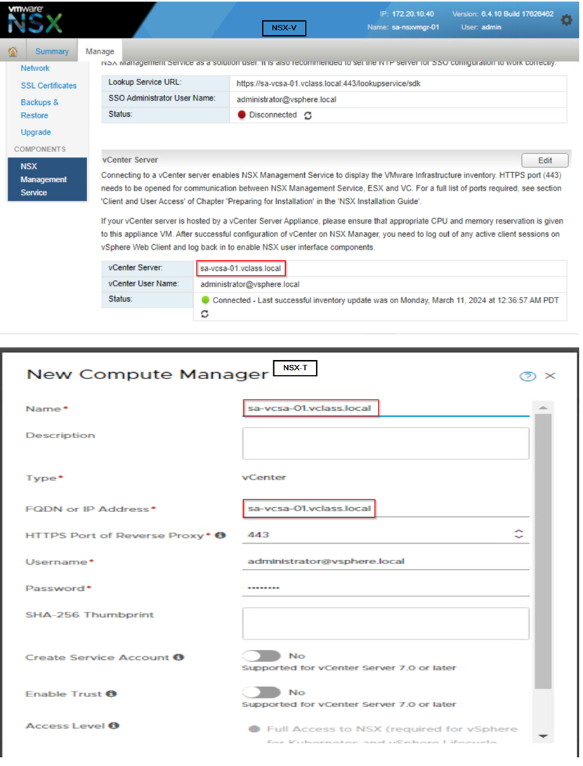
Step 1: Adding the compute manager. Here make sure how NSX-V is registered with vCenter make sure you register the vCenter with NSX-T in same way.
For example: On NSX-V vCenter is registered with FQDN then on NSX-T also we need to register vCenter with FQDN. Below we can observe in current environment we have used FQDN on NSX-V, therefore on NSX-T we are proceeding with FQDN.
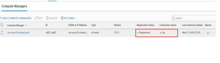
Once the vCenter is added the registration should be successful and status should be up.
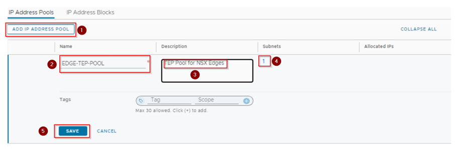
Step 2: Create an IP pool for the edge tunnel end points. The IP pool range should not overlap it should be unique and should not be used on NSX-V. We check the IP range what we use in NSX-T for Edges should be reachable with NSX-V host prepared with VTEPs. So, the physical network configuration should be in place.
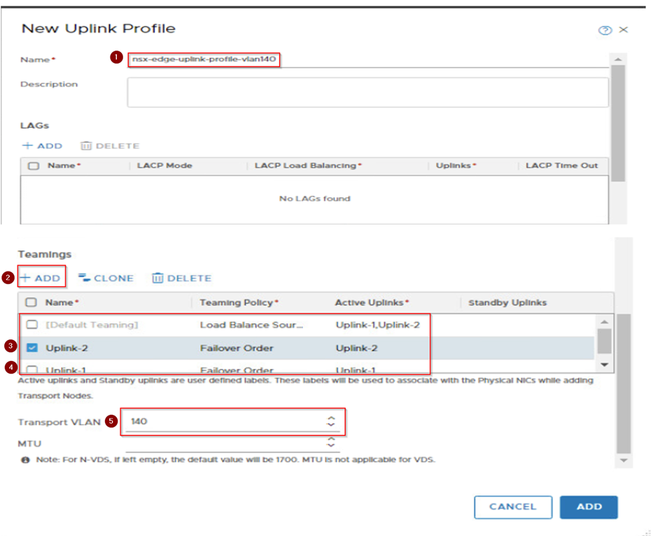
Step 3: Configure the Uplink profile and uplink segments for the North-South routing for the edges. If your environment is using the Active-Active scenario then configure the teaming policy for the uplinks and call it out on the VLAN transport zone.
Here if you observe we have added the active 2 uplinks and failover with one uplink teaming policies. This configuration will provide redundancy for the traffic if any one edge goes down.
Transport vlan is 140 this can be same as what we use in NSX-V or different. However, if it’s different make sure after the Edge deployment the TEP IP address are reachable with NSX-V host TEPs.
Step 4: Here we will use default vlan transport zone and call the uplinks what we have configured on uplink profiles of Edges which we created in previous step.

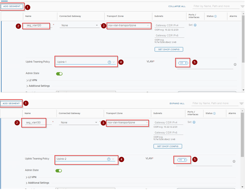
Step 5: Create Uplink-Segment for Tier-0. Here provide a name then select the transport zone, uplink teaming policy and Vlan.
Here we are creating two segments seg_vlan120 and seg_vlan130. On seg_vlan120 we select the teaming policy as Uplink-1 and seg_vlan130 we select the teaming policy as Uplink-2.
Step 6: Deploy the Edges as per the services requirements used in the environment (i.e. size of edge node either Small, Medium, or Large) using the OVF. Don’t deploy the edges via the NSX-T UI as per the best practices.
Here we are deploying the two edges via ovf as shown below,
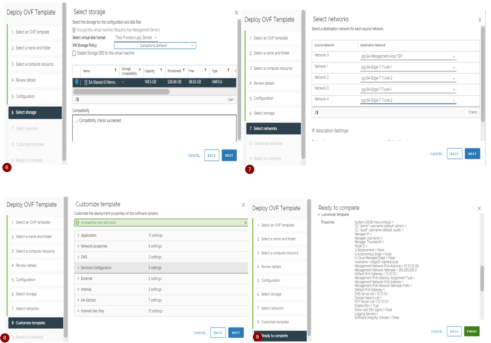
Follow and provide the details on Deploy OVF Template tab
- Select the OVF template
- Provide the VM name for the edge VM.
- Select the compute resource.
- Reveiw the details.
- Select the deployment configuration (Small, Medium, Large or XLarge). Here we have used large type.
- Select the storge.
- Select the Network. Here we select the management network for first adapter and other 2 adapter with Uplink port group which will be used for carrying the routing traffic. The third and Fourth adapters will be disconnected before we power on the edges.
- Customize Template. Here we provide the root, admin, audit passwords, IP address, gateway, DNS, hostname and NTP details.
- Ready to complete. Review the details provided and hit finish.

Step 7: Once required number of edges are deployed then we need to join these edges with NSX-T appliance via below procedure.
1.Open a SSH or console session to the NSX Manager appliance. Run get certificate API thumbprint command and note it down.
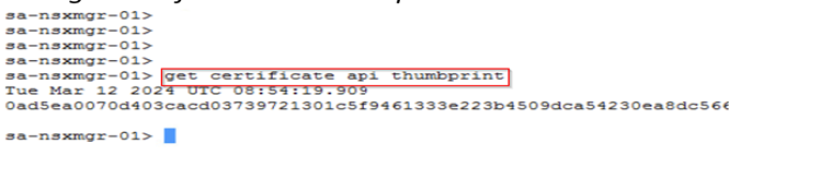
2.Open an SSH session or console session to the NSX Edge node VM. Run join management-plane <NSX_Manager_IP> thumbprint <NSX_Manager_thumbprint username admin command which make the edge node to register it with NSX-T manager.

Step 8: Once the edges are joined the NSX Manager. Now here we need to make a note if you are using the fixed topology then Migration coordinator will configure the edges while doing migration. In our case here we are using the User define topology we need to configure the edges and then form a cluster.
Here below step will guide you for configuring the edge nodes.
1.Now when you see the edges nodes the configuration state is pending/not configured. Click on it and configure the Transport zone, uplink profile, IP and select the uplinks for the edge node. Once we hit save, we can see after some time the edge node configuration state is successfully.

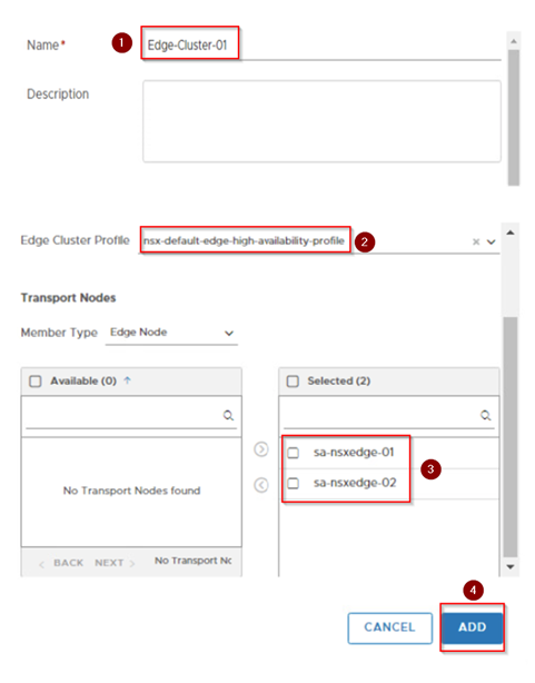
2.Create an edge cluster and add the edges to it to form a cluster.
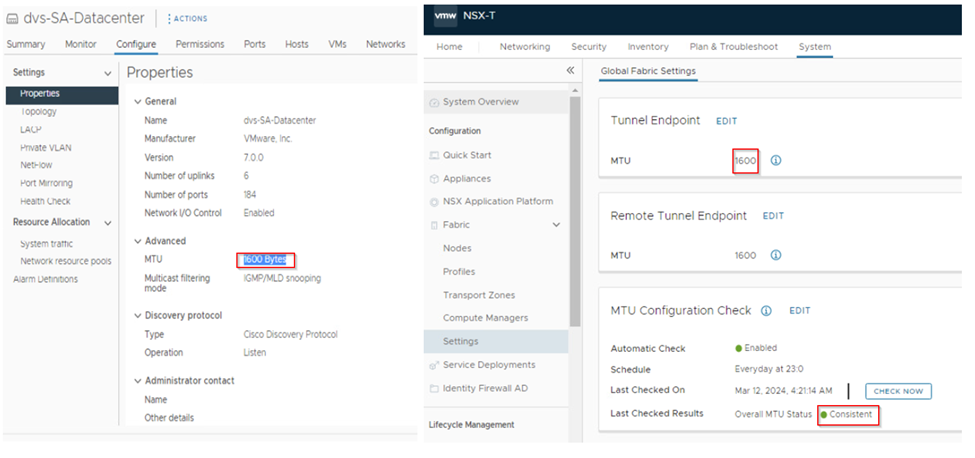
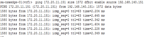
Step 9: Once the edges are configured and added in cluster next step will be the ping reachability test from the edges to NSX-V hosts. This should be successful with MTU 1600 or more. If not check the VDS what is the MTU configure and as well on the NSX-T configuration settings check the MTU.
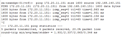
1.Do the ping test from edge use command ping <ESXI VTEP IP> size <MTU> source <Edge TEP IP> or ping <ESXI VTEP IP> size <MTU> dfbit enable source <Edge TEP IP>.
2.Successful ping confirms that the traffic from Edge to EXSI is through and after edge cutover workload will be reachable.
3.If the ping is not successfully, please check the VDS port group mapped with edge is trunk and MTU is configured as required. Make sure there is no firewall in between the host VTEP and Edge TEP subnet, if yest make sure the traffic is allowed on firewall.
Step 10: Now we create the Teir-0(T0) and configure the static or dynamic routing on T0 for north-south(N-S) routing based on the environment what is used on NSX-V. In this environment we are using dynamic routing BGP for N-S routing. The Neighborship should keep up with T0s to physical Environment (routers or L3 switches).
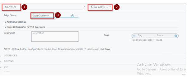
1.Creating the T0- here we provide the name, select the edge cluster, and set the HA mode to active-active and hit on save.
2. Now we edit the created T0 to configure the interface and the routing protocol in here BGP and then check the connection is established or not. Here we will be configuring total 4 interfaces 2 for each edge.
Here is how the configuration will be.
On Edge-1 it will look like below:
Interface of T0:
Interface name: Edge-1-Uplink-1
Segment: seg_vlan120
IP address: from the vlan 120 subnet
Edge node: edge node 1
Interface of T0:
Interface name: Edge-1-Uplink-2
Segment: seg_vlan130
IP address: from the vlan 130 subnet
Edge node: edge node 1
On Edge-2 it will look like below:
Interface of T0:
Interface name: Edge-2-Uplink-1
Segment: seg_vlan120
IP address: from the vlan 120 subnet
Edge node: edge node 1
Interface of T0:
Interface name: Edge-2-Uplink-2
Segment: seg_vlan130
IP address: from the vlan 130 subnet
Edge node: edge node 1

3.Configuring the BGP.Here we will provide the local AS and then add the neighbors.

4.Now we will configure the route re-distribution.Here make sure we redistribute and advertise the requried routes only as per the environment.
Here we have configured as below,
1.On T0 we will redistribute static and connected route.
2.For T1 we will advertise only NAT IP we will not advertise the connected and static routes.

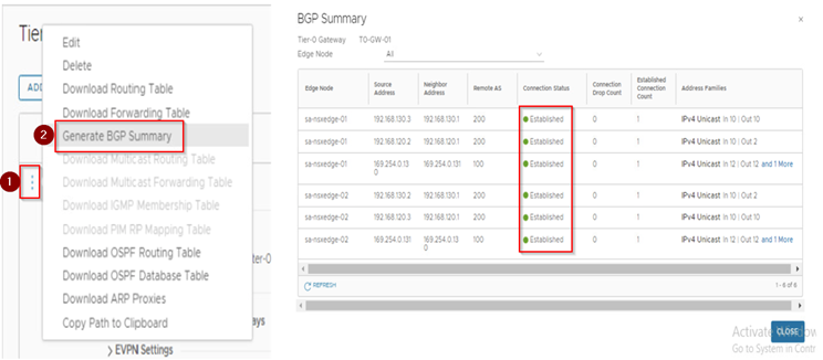
5.Once we are done with the BGP and redistribution configuration.we check the BGP neighborship by generating the BGP summary report.
This document marks the successful completion of the NSX-T deployment and configuration, which concludes part 1 of our blog. In this phase, the following steps were executed:
1. Verification of the NSX-V environment for migration readiness.
2. Deployment of the NSX-T appliance with compatibility considerations.
3. Creation of uplink segments and configuration of the uplink profile with a teaming policy for the edges.
4. Deployment of the edges and integration with NSX-T manager.
5. Conducting a ping test between Edge TEP and NSX-V Host VTEP.
6. Establishment of T0 and uplink configuration with BGP neighborship.
These steps were executed with the utmost precision, in compliance with the best practices and guidelines of the NSX-T deployment and configuration process. The successful completion of this phase sets the foundation for the next stage in this initiative.
The forthcoming blog post will expound on a subsequent step in which the NSX-T account will be added to vRealize Automation (vRA), followed by its transition into Maintenance Mode (MM). Subsequently, JSON will be generated, and the Migration Coordinator will be enabled. This post aims to provide a comprehensive and detailed guide on these crucial processes.
Below are the Reference Links,
https://interopmatrix.vmware.com/Interoperability
https://docs.vmware.com/en/VMware-NSX-T-Data-Center/3.2/installation/GUID-3E0C4CEC-D593-4395-84C4-150CD6285963.html
https://docs.vmware.com/en/VMware-NSX-T-Data-Center/3.2/migration/GUID-7899A104-2662-4FC9-87B2-F4688FAEBBBA.html
I’m glad to hear that you’re open to feedback. If you have any specific concerns or questions, please let me know and I’ll do my best to address them.

March 28, 2024 at 7:17 pm
[…] Based on VMware technologies, this site likely provides information and learnings related to software-defined data centers.VMware NSX for network virtualization for IT professionals and organizations using VMware products to optimize their infrastructure, enhance security, and streamline operations. « Migration of the NSX-V to NSX-T integrated with vRA-Part-1 […]
April 23, 2024 at 6:51 pm
[…] hope you may have gone through the first two parts of the migration process, if not here is the part-1 and part-2 […]